Product Description
PROFESSIONAL MANUFACTURE
— SINCE 1995
R RF Series R series 7.5KW energy saving helical gear motors
Chinese electric motor speed reducer is widely used in mining machinery, chemical industry,steel metallurgy, light
industry,environmental protection, paper making, printing, lifting transport, food industry and so on.
Main Series Product: R series helical gear motor reducer, K series spiral bevel gear reducer, NGW, P series planetary gear reducer, H B series helical gearbox, Z (ZDY, ZLY, ZSY, and ZFY) serial hard tooth surface cylindrical gearbox reducer, D (DBY and DCY) serial hard tooth surface cone gear reducer, cycloidal speed reducer, etc. Meanwhile, map sample processing business can be undertaken.
Product Description
It realized serialization and modularization with compact structure and wide range of transmission ratio.
The transmission efficiency reach up to 96%.
The gear processed by Carburizing, Nitriding & Grinding.
High efficiency, superior performance with less energy consumption.
High precision gear, steady transmission, low noise, large load capacity, long service life.
Support various of installation method.
Product Parameters
|
Size
|
R 57
|
R 67
|
R 77
|
R 87
|
R 97
|
R 107
|
R 137
|
R 147
|
R 167
|
|
Structure
|
R RF
|
|
Input power rating(kw)
|
0.18-7.5KW
|
0.18-7.5KW
|
0.18-11KW
|
0.55-22KW
|
0.55-30KW
|
2.2-45KW
|
5.5-55KW
|
11-90KW
|
11-160KW
|
|
Ratio
|
4.39-186.89
|
4.29-199.81
|
5.21-195.24
|
5.36-246.54
|
4.49-289.74
|
5.06-249.16
|
5.15-222.60
|
5.00-163.31
|
10.24-229.71
|
|
Permissible torque N.m
|
450
|
600
|
820
|
1550
|
3000
|
4300
|
8000
|
1300
|
18000
|
Model selection for washing machine Gear Box Transmission:
Closely using the ideal reduction ratio.
Reduction ratio = servo motor speed / reducer output shaft speed
Torque calculation: Torque calculation is very important for the life of reducer, and pay attention to whether the maximum torque value (TP) of acceleration exceeds the maximum load torque of the reducer.
The applicable power is usually the applicable power of the servo models on the market, the applicability of the reducer is very high, the working coefficient can be maintained above 1.2, but the choice can also be based on their own needs to decide. industrial helical gearbox. H PV series High quality Right Angle Unique speed reducer HB helical gearbox / gear box.
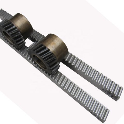
Detailed Photos
Chinese Speed Reducer/industrial helical gearbox is a mechanical transmission in many fields of the national economy. The product categories covered by the industry include all kinds of gear reducer, planetary gear reducer and worm reducer, as well as various special transmission devices such as speed increasing device, speed control Devices, including various types of flexible transmission devices, such as compound transmission. Products and services in the field of metallurgy, nonferrous metals, coal, building materials, ships, water conservancy, electricity, construction machinery and petrochemical industries.
In all fields of national economy and national defense industry, gearbox products have a wide range of applications. Food light industry, electric machinery, construction machinery, metallurgy machinery, cement machinery, environmental protection machinery, electronic appliances, road construction machinery, water conservancy machinery, chemical machinery, mining machinery, conveyor machinery, building materials machinery, rubber machinery, petroleum machinery and other industries have strong demand of Reducer products.
Packaging & Shipping
Application
| Driven machines |
| Waste water treatment |
Thickeners,filter presses,flocculation apparata,aerators,raking equipment,combined longitudinal and rotary rakes,pre-thickeners,screw pumps,water turbines,centrifugal pumps |
Dredgers |
Bucket conveyors, dumping devices, carterpillar travelling gears, bucket wheel excavators as pick up, bucket wheel excavator for primitive material, cutter head, traversing gears |
| Chemical industry |
Plate bending machines, extruders, dough mills, rubbers calenders, cooling drums, mixers for uniform media, agitators for media with uniform density, toasters, centrifuges |
Metal working mills |
plate tilters, ingot pushers, winding machines, cooling bed transfer frames, roller straigheners, table continuous intermittent, roller tables reversing tube mills, shears continuous, casting drivers, reversing CZPT mills |
| Metal working mills |
Reversing slabbing mills. reversing wire mills, reversing sheet mills, reversing plate mill, roll adjustment drives |
Conveyors |
Bucket conveyors, hauling winches, hoists, belt conveyors, good lifts, passenger lifts, apron conveyors, escalators, rail travlling gears |
| Frequency converters |
Reciprocating compressors |
| Cranes |
Slewing gears, luffing gears, travelling gears, hoisting gear, derricking jib cranes |
Cooling towers |
Cooling tower fans, blowers axial and radial |
| Cane sugar production |
Cane knives, cane mills |
Beet sugar production |
Beet cossettes macerators, extraction plants, mechanical refrigerators, juice boilers, sugar beet washing machines, sugar beet cutter |
| Paper machines |
Pulper drives |
Cableways |
Material ropeways, continuous ropeway |
| Cement industry |
Concrete mixer, breaker, rotary kilns, tube mills, separators, roll crushers |
|
|
Company Profile
Established in 1995 , HangZhou Boji Machinery is a professional manufacturer and exporter that is concerned with the design, development and production of Gearbox Speed Reducer. We are located in HangZhou of ZheJiang Province, with convenient transportation access. With our own brand “TianQi”, all of our products comply with international quality standards and are greatly appreciated in a variety of different markets throughout the world.
Our company possesses complete machining center, lathe, gear shaping machine, gear milling machine, gear grinding machine and assembling lines. Our well-equipped facilities and excellent quality control throughout all stages of production enables us to guarantee total customer satisfaction.
Besides, In 2005,we attained ISO9001 certification. As a result of our high quality products and outstanding customer service, we have gained a global sales network CZPT South America, Saudi Arabia, Vietnam, Pakistan, Philippines, South Africa and other countries and regions.
With rich export experience, high quality products, competitive prices, good service and in-time delivery, we certain that we can meet all of your requirement and exceed your expectations. Our feature is bright with new cooperative relationships with companies from all over the world. We look CZPT to speaking with you to future discuss how we can be of service to you.
FAQ
1. Who are we?
We are the Factory, with over 25 years of production experience, based in ZheJiang , China, start from 1995,sell to Domestic Market(50.00%),Mid East(10.00%),Southeast Asia(10.00%),Western Europe(5.00%),South America(5.00%),Eastern Europe(5.00%),Eastern Asia(5.00%),North America(3.00%),Africa(2.00%),Southern Europe(2.00%),South Asia(2.00%),Central America(1.00%).
2. Can you customize according to our requirements?
Yes, we can design nonstandard products according to customer’s drawing and sample.
3.What can you buy from us?
speed reducer,gearbox,gear motor,pump,crusher
4. Why should you buy from us not from other suppliers?
Founded in 1995, with over 20 years of production experience and credibility. With professional engineer team, advanced technology production and skilled workers.Specialized in the production of reducer. Map sample processing business can be undertaken.
5. What services can we provide?
Accepted Delivery Terms: FOB,CFR,CIF,EXW,DDP,DDU,Express Delivery;
Accepted Payment Currency:USD,EUR,JPY,CAD,AUD,HKD,GBP,CNY,CHF;
Accepted Payment Type: T/T,L/C,Credit Card,PayPal,Western Union,Cash;
Language Spoken:English,Chinese,Spanish,Japanese,Portuguese,German,Arabic,French,Russian,Korean,Hindi,Italian
| Application: |
Motor, Machinery |
| Hardness: |
Hardened Tooth Surface |
| Installation: |
Horizontal Type |
| Layout: |
Coaxial |
| Gear Shape: |
Helical Gear |
| Step: |
Double-Step |
| Samples: |
US$ 200/Piece
1 Piece(Min.Order)
|
Request Sample
|
| Customization: |
Available
|
Customized Request
|

The Basics of Designing a Cyclone Gearbox
Compared to conventional gearboxes, the cycloidal gearbox offers a number of advantages including a higher ratio of transmission, robustness against shock loads, and greater positioning accuracy. However, designing a cycloidal gearbox can be complicated. This article will discuss some of the basic design principles. In addition, it will cover topics such as size, position accuracy, and transmission ratios.
Basic design principles
Unlike a conventional ring gear, a cycloidal gearbox uses a cycloidal disc to provide torque multiplication. The output direction of the cycloidal gear disc is opposite to the rotation of the input shaft. This allows for more compact gear construction. It also allows for increased load capacity.
Cycloid drive kinematics can appear complex, but they are actually quite simple. Instead of rotating around the center of gravity like conventional gears, the cycloidal disc rotates around fixed pins. This provides a higher reduction ratio.
To reduce vibrations and noise, multiple cycloidal discs are used. This allows for uniform distribution of forces on the carrier pin devices. This also provides a better rotational balance. In addition, multiple cycloidal discs reduce the axial moment of the carrier pin devices.
The cycloidal gear disc is supported by a separate gear disc bearing. This design provides a low component count and reduces wear. This type of kinematics can also be used in an electric motor with a high power density.
The cycloidal gear disc provides a high reduction ratio, which allows for compact construction. Unlike a ring gear, the cycloidal disc has fewer teeth. It also provides a higher reduction ratio, which is advantageous for high rotational input speed applications.
Cycloid gear discs have cylindrical holes, which allow for carrier pin devices to protrude through them. This is useful because the carrier pin devices can roll along the inside wall of the cylindrical hole in the gear disc.
A load plate is also used to provide anchorage for external structures. This plate contains threaded screw holes arranged 15mm away from the center. It has a 9mm external diameter and a 3mm through hole.
Transmission ratios up to 300:1
cycloidal gearboxes are used in a wide range of applications, from machine tools to medical imaging devices. Compared to planetary gearboxes, they offer superior positioning accuracy, torsional stiffness, backlash, and fatigue performance.
Cycloid gearboxes are also capable of transmitting more torque than planetary gears. In addition, they have a lower Hertzian contact stress and higher overload protection. Cycloid gearboxes are able to provide transmission ratios up to 300:1 in a small package.
Cycloid gears also have lower backlash over extended periods, making them an ideal choice for applications with critical positioning accuracy. Cycloid gearboxes also have good wear resistance, as well as low friction. Cycloid gears are lightweight and have good torsional stiffness, making them ideal for applications with heavy loads.
Cycloid gearboxes have several different designs. They can provide transmission ratios up to 300:1 without the need for additional pre-stages. Cycloid gears also require more accurate manufacturing processes than involute gears. Cycloid gearboxes can also be used for applications that require high power consumption, and can withstand shock loads.
Cycloid gearboxes can be adapted to fit most common servomotors. They have a modular design, all-round corrosion protection, and easy installation. Cycloid gears have a radial clamping ring, which reduces inertia by up to 39%.
CZPT Precision Europe GmbH, a subsidiary of CZPT Group, has developed an innovative online configurator to simplify the configuration of gearboxes. CZPT cycloidal gearheads are precision-built, robust, and reliable. They have a two-stage reduction principle, which minimises vibration and provides even force distribution.
Cycloid gears are capable of providing transmission ratios from 30:1 to 300:1. Cycloid gearboxes can achieve high gear ratios because they require fewer moving parts, and they have a low backlash.
Robustness against shock loads
Unlike conventional gearboxes that are easily damaged by shock loads, the cycloidal gearbox is extremely robust. It is a versatile solution that is ideally suited for handling equipment, food manufacturing, and machine tools.
The mechanical construction of a cycloidal gearbox consists of several mechanical components. These include cycloidal wheels, bearings, transformation elements, and needles. In addition, it has high torsional stiffness and tilting moment. It is also accompanied by highly nonlinear friction characteristic.
In order to assess the robustness of the cycloidal gearbox against shock loads, a mathematical model was developed. The model was used to calculate the stress distribution on the cycloid disc. This model can be used as a basis for more complex mechanical models.
The model is based on new approach, which allows to model stiction in all quadrants of the cycloid gear. In addition, it can be applied to actuator control.
The mathematical model is presented together with the procedure for measuring the contact stress. The results are compared to the measurement performed in the real system. The model and the measurement are found to be very close to each other.
The model also allows for the analysis of different gear profiles for load distribution. In addition, it is possible to analyze contact stresses with different geometric parameters. The mesh refinement along the disc width helps to ensure an even distribution of contact forces.
The stiction breakaway speed is calculated to the motor side. The non-zero current is then derived to the input side of the gearbox. In addition, a small steady phase is modeled during the speed direction transition. The results of the simulation are compared to the measurement. The results show that the model is extremely accurate.
Positioning accuracy
Getting the correct positioning accuracy from a cycloidal gearbox is no small feat. This is because the gears are compact, and the clearances are relatively small. This means you can expect a lot of torque from your output shaft. However, this is only part of the picture. Other concerns, such as backlash, kinematic error, and loading are all important considerations.
Getting the best possible positioning accuracy from a cycloidal gearbox means choosing a reducer that is well-made and correctly configured. A properly-selected reducer will eliminate repeatable inaccuracies and provide absolute positioning accuracy at all times. In addition, this type of gearbox offers several advantages over conventional gearboxes. These include high efficiency, low backlash, and high overload protection.
Getting the correct positioning accuracy from a gearbox also involves choosing a supplier that knows what it is doing. The best vendors are those who have experience with the product, offer a wide variety, and provide support and service to ensure the product is installed and maintained correctly. Another consideration is the manufacturer’s warranty. A reputable manufacturer will offer warranties for the gearbox. The aforementioned factors will ensure that your investment in a cycloidal gearbox pays off for years to come.
Getting the correct positioning accuracy from your cycloidal gearbox involves choosing a manufacturer that specializes in this type of product. This is particularly true if you are involved in robotics, automated painting, or any other industrial process that requires the best possible accuracy. A good manufacturer will offer the latest technology, and have the expertise to help you find the best solution for your application. This will ensure your product is a success from start to finish.
Size
Choosing the right size of cycloidal gearbox is important for its efficient operation. However, it is not a simple task. The process involves complex machining and requires the creation of many parts. There are different sizes of cycloidal gearboxes, and a few basic rules of thumb can help you choose the right size.
The first rule of thumb for choosing the right size of cycloidal gearboxes is to use a gearbox with the same diameter of the input shaft. This means that the gearbox must be at least 5mm thick. The cycloid will also require a base and a bearing to hold the driveshaft in place. The base should be large enough to house the pins. The bearing must be the same size as the input shaft.
The next rule of thumb is to have a hole in the cycloid for the output shaft. In this way, the output will be back-drivable and has low backlash. There should be at least four to six output holes. The size of the holes should be such that the centerline of the cycloid is equal to the size of the center of the bearing.
Using a Desmos graph, you can then create the gear parameters. The number of pins should be equal to the number of teeth in the cycloidal gear, and the size of the pins should be twice the size of the gear. The radius of the pins should be equal to the value of C from Desmos, and the size of the pin circle should be equal to the R value.
The final rule of thumb is to ensure that the cycloid has no sharp edges or discontinuities. It should also have a smooth line.


editor by CX 2023-11-13
 NYLON, OIL NYLON, POM, UHMW-PE, PU, PETP, Pc, PTFE, PVDF, PPS, PEEK, PAI, PI, PBI ect.
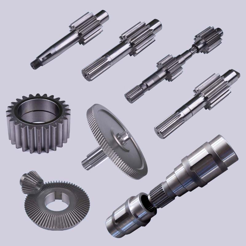 sets of German Ipsen ambiance furnace lines.
 of energy get offs is 540rpm which could be compared with all the correct running speeds of hydraulic pumps.Unique input working speeds can also be ideal,provided the PTO gearbox output speed will not exceed 3000 rpm.
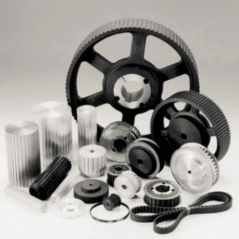 bushing: SPZ, SPA, SPB, SPC; up to 10 grooves
 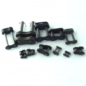 amount of components, has proved to be specifically thriving in higher duty, higher abrasion application exactly where lubrication just isn’t doable. Our steel bush chains have been proving efficiency in mill duty centrifugal discharge elevators within the more difficult applications encountered during the cement marketplace.


